What Is a Backup Generator and How Does It Work?

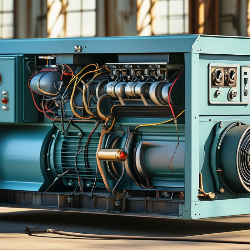
When the lights fail, a Backup Generator can keep a home, clinic, data room, or factory operating. It does not create electricity from nowhere. Instead, an engine burns diesel, natural gas, or propane to rotate an alternator. The alternator then converts mechanical energy into electrical power. An automatic transfer switch detects a utility failure and moves selected circuits to generator power, often within seconds.

The need is practical, not theoretical. The U.S. Energy Information Administration’s Annual Electric Power Industry Report shows that American customers experience several hours of power interruptions in a typical year, especially when major events are included. Uptime Institute’s Annual Outage Analysis also continues to identify power-related failures as a leading cause of serious data-center outages. These findings explain why businesses study generator capacity, fuel storage, ventilation, and maintenance before an emergency occurs.

Electrical-safety educator Mike Holt emphasizes, “A transfer switch prevents generator power from backfeeding utility lines.” That detail is easy to overlook. It can protect repair crews and prevent dangerous equipment damage. A generator is not a magic box.

A dependable system still needs weekly visual checks, battery testing, scheduled load-bank testing, and clean fuel. Grand View Research has reported continued growth in the global generator market, driven by unreliable grids and expanding commercial demand. Yet buying a larger machine is not always better. Oversizing can cause wet stacking, wasted fuel, and poor performance at light loads. This guide explains how a Backup Generator works, what its major components do, and where real-world assumptions often fail.

What Is a Backup Generator and How Does It Work?

What a Backup Generator Is: Standby Ratings Under ISO 8528

What Is a Backup Generator and How Does It Work?

A backup generator supplies electricity when the utility connection fails. Its engine burns fuel, turns an alternator, and produces electrical power. An automatic transfer switch detects the outage and moves selected loads to the generator, often within seconds.

The more important question is its standby rating. Under ISO 8528-1, Emergency Standby Power, or ESP, describes equipment designed for temporary outage support. The load may vary during an emergency. However, the generator is not intended for continuous prime-power service. Its nameplate rating should match the actual emergency load, not the total building capacity. A 500 kW ESP rating does not mean the unit should carry 500 kW every day.

ISO 8528 also identifies Prime Running Power, Limited-Time Running Power, and Continuous Operating Power. These ratings involve different operating patterns, load factors, and maintenance expectations. Industry guidance commonly treats ESP units as limited-use equipment, while prime-rated units support longer, variable operation. The U.S. Energy Information Administration’s 2023 reliability data shows that major electric disturbances continue to affect customers across the country. That risk makes correct rating selection practical, not theoretical. A cold engine, long fuel line, or poorly tested transfer switch can still cause failure. Real sites are messier. Engineers should review temperature, altitude, starting loads, fuel storage, and maintenance records before accepting the label. A rating alone never proves readiness.

What Is a Backup Generator and How Does It Work?

Nominal AC output waveform for a 230 V RMS, 50 Hz backup generator

1. Utility failure

An automatic transfer system detects loss of utility power and sends a start signal to the generator.

2. Engine and alternator

The engine converts fuel energy into rotation, while the alternator converts that rotation into electrical power.

3. Standby rating

Under ISO 8528, generator performance is assessed according to the intended application and operating requirements, rather than by waveform voltage alone.

The chart shows an idealized single-cycle sine wave. A 230 V RMS supply has a calculated peak voltage of approximately 325 V, and a 50 Hz cycle lasts 20 milliseconds. Actual generator output is regulated by the alternator and control system and may vary with load, speed, and operating conditions.

How Fuel Drives an Alternator to Produce 50 or 60 Hz Electricity

What Is a Backup Generator and How Does It Work?

How Fuel Drives an Alternator to Produce 50 or 60 Hz Electricity

A backup generator converts stored fuel into electrical power during an outage. Its engine burns diesel, natural gas, or another approved fuel. The resulting combustion pushes pistons, turning a crankshaft and alternator. Inside the alternator, a rotating magnetic field passes through copper windings. This movement creates alternating current for connected loads.

Frequency depends mainly on engine speed and pole count. A four-pole alternator turning at 1,500 revolutions per minute produces 50 Hz electricity. At 1,800 revolutions per minute, it produces 60 Hz. A governor adjusts engine speed, while an automatic voltage regulator controls output voltage. ISO 8528-1 classifies generator sets by performance and operating requirements. The system must remain stable when motors start suddenly. That part is often underestimated.

The International Energy Agency’s Electricity 2024 report estimates that data centers used about 460 terawatt-hours globally in 2022. Demand could exceed 1,000 terawatt-hours by 2026. Reliable standby power is becoming more important, although a generator is not a perfect substitute for grid planning.

Tips: Check fuel quality, coolant, batteries, and exhaust ventilation during scheduled tests. Record voltage and frequency under load. A no-load test can hide problems. Follow the maintenance intervals in the equipment manual, and ask a qualified technician to verify transfer-switch operation.

How Automatic Transfer Switches Meet NFPA 110’s 10-Second Requirement

What Is a Backup Generator and How Does It Work?

A backup generator supplies electricity when normal utility power fails. It usually combines an engine, alternator, fuel system, controls, and protective devices. The automatic transfer switch is the critical link between the building and the generator.

When the switch detects abnormal voltage, it sends a start signal to the generator. The engine accelerates, while controls check output voltage and frequency. Once the power is stable, the switch disconnects the utility and connects the emergency source. For NFPA 110 Type 10 applications, the emergency power supply system must provide power to designated loads within 10 seconds after normal power loss. This requirement concerns the complete system, not only the generator’s starting speed.

Timing is measured in real conditions. Cold fuel, weak batteries, incorrect sensing settings, or overloaded circuits can cause delays. A commissioning technician should test simulated outages, record start and transfer times, and verify load performance. Small details matter. The switch must also prevent unsafe backfeeding and return to utility power in a controlled sequence. A ten-second target is not a promise that every installation will achieve it automatically. Local code adoption, system classification, maintenance quality, and site conditions still need review. That part is easy to underestimate.

What Is a Backup Generator and How Does It Work? - How Automatic Transfer Switches Meet NFPA 110’s 10-Second Requirement

Data Dimension Description Typical or Code-Related Information Role in Backup Power Operation
Backup Generator An engine-driven generator set that produces electrical power when the normal utility supply is unavailable. Common configurations use diesel, natural gas, or liquid propane engines connected to an alternator. Supplies standby or emergency loads after receiving a start command and reaching acceptable operating conditions.
Normal Power Source The utility or primary electrical service used during normal operating conditions. The automatic transfer switch continuously monitors voltage, frequency, and phase-related conditions as applicable. Provides power to the connected load until an unacceptable outage or disturbance is detected.
Automatic Transfer Switch (ATS) A switching device that transfers designated electrical loads between normal and alternate power sources. An ATS typically includes source monitoring, control logic, electrically operated switching equipment, and mechanical or electrical interlocking. Starts the generator when needed, transfers the load to the alternate source, and returns the load after normal power is stable.
Utility Failure Detection The ATS identifies when the normal source falls outside programmed voltage, frequency, or phase limits. Detection settings and time delays are adjustable according to the system design and equipment requirements. Prevents unnecessary generator starts caused by brief voltage disturbances or momentary interruptions.
Engine Start Signal A control signal sent by the ATS to the generator controller after a qualifying normal-power failure. The generator controller initiates cranking, fuel delivery, ignition or combustion, and engine acceleration. Begins the emergency power sequence without requiring manual intervention.
Generator Stabilization The period during which the engine and alternator reach acceptable voltage and frequency before load transfer. The required time depends on generator size, engine type, starting conditions, load characteristics, and control settings. Ensures the alternate source is suitable for connection and reduces the risk of transferring loads to unstable power.
NFPA 110 Classification NFPA 110 classifies emergency and standby power systems by performance and installation requirements. Level 1 systems are used where failure of the equipment could result in loss of human life or serious injury; Level 2 systems support less critical applications. Defines the level of reliability, maintenance, testing, and performance expected from the emergency power system.
NFPA 110 Type 10 Requirement Type 10 identifies an emergency power supply system intended to restore power within the specified maximum time. For applicable Level 1 emergency systems, power is required to be available at the transfer switch load terminals within 10 seconds after loss of the normal source, subject to the adopted edition and applicable requirements. Sets the performance target for the complete emergency power sequence, not merely the engine’s start time.
Load Transfer The ATS disconnects the designated load from the normal source and connects it to the generator source. Most transfer switches use an open-transition sequence, while closed-transition designs briefly parallel sources only when permitted and properly engineered. Restores power to emergency circuits such as life-safety, critical equipment, communications, or legally required standby loads.
Emergency Loads Electrical loads selected to remain operational during a normal-source failure. Examples may include emergency lighting, fire alarm systems, smoke control equipment, medical equipment, elevators, pumps, or communications systems, depending on the facility. Allows essential functions to continue while nonessential loads remain disconnected or are connected through separate controls.
Generator Capacity The maximum electrical output the generator can provide under specified operating conditions. Capacity is commonly expressed in kilowatts (kW) or kilovolt-amperes (kVA), with ratings selected for continuous, prime, or standby operation. Determines which loads can be supported and how the generator responds to motor starting, inrush current, and load additions.
Return to Normal Power The ATS transfers the load back after the normal source returns and remains stable for the programmed retransfer delay. A retransfer delay helps avoid repeated switching during unstable utility restoration. Allows the generator to run without load for a cool-down period before the controller stops the engine.
Testing and Maintenance Routine inspection, exercising, load testing, fuel-system checks, battery checks, and ATS testing verify system readiness. Testing frequency and procedures depend on the applicable NFPA requirements, local regulations, facility risk category, and equipment instructions. Helps confirm that the generator can start, stabilize, transfer loads, carry the required demand, and retransfer correctly during an actual outage.

Note: NFPA 110 requirements should be applied using the edition adopted by the authority having jurisdiction, together with the facility’s electrical design, local codes, and equipment documentation.

How to Size Generator Capacity for Running and Motor-Starting Loads

A backup generator supplies electricity when the utility source fails. An automatic transfer switch detects the outage and signals the generator to start. The engine turns an alternator, which produces electrical power for selected circuits. Within seconds, lights, refrigeration, pumps, and other essential equipment can receive power.

Generator sizing must separate running watts from starting watts. Running watts keep equipment operating continuously. Starting watts cover the brief surge required by motors. A refrigerator may run at 700 watts but need 2,200 watts during startup. A well pump can create an even sharper demand. List every load, record its running wattage, and identify the largest motor-starting surge. Do not simply add nameplate numbers without checking their meaning.

The generator should handle the combined running load plus the largest expected starting surge. For example, a 4,000-watt running load with a 2,000-watt motor surge may require at least 6,000 watts. Add practical headroom, often 20% to 25%, for voltage stability and future equipment. Large motors may start more smoothly with staged loads or soft-start controls. Kilovolt-amperes also matter when power factor is low. The first estimate is rarely perfect. A pump may start under pressure, not at an empty load. Verify measurements with a qualified electrician, especially where transfer equipment and hardwired circuits are involved. Safety depends on details.

Fuel, Emissions, and Safety: EPA Tier 4 Final and OSHA Requirements

A backup generator converts fuel into electrical power during an outage. A diesel engine turns an alternator, creating electricity for selected circuits. The fuel tank must support the expected load and runtime. Poor fuel quality can clog filters and damage injectors. It happens more often than people admit.

EPA Tier 4 Final standards target emissions from nonroad diesel engines. The EPA’s Tier 4 fact sheet reports major reductions in particulate matter and nitrogen oxides compared with earlier engine tiers. Modern systems may use diesel oxidation catalysts, particulate filters, and selective catalytic reduction. These controls need correct temperatures and regular maintenance. Low-load operation can increase deposits and reduce efficiency. EPA emissions rules do not eliminate indoor-air risks. Exhaust still contains carbon monoxide, which can accumulate quickly in enclosed spaces.

OSHA 29 CFR 1910.147 requires hazardous-energy control during servicing. Workers should isolate electrical and mechanical energy before opening panels or replacing parts. OSHA 29 CFR 1910.1200 also requires hazard communication for diesel fuel, lubricants, and exhaust-treatment fluids. Ventilation matters. Carbon-monoxide monitoring adds another layer of protection, especially near loading docks or temporary enclosures. NFPA 110 guidance emphasizes routine testing, automatic transfer equipment, and documented maintenance. A monthly test is useful, but it may not reveal every failure. Fuel aging, battery weakness, blocked exhaust paths, and ignored alarms still deserve hands-on inspection.

Need Help?
X

Ready to Talk?

Our team is ready to connect.