What Are the Main Transformer Core Types?

Transformer Core Types determine how efficiently a transformer carries magnetic flux, manages heat, and withstands mechanical stress. The choice is not merely structural. It affects losses, noise, size, maintenance, and service life.

The U.S. Department of Energy estimates that distribution transformers account for roughly 60–80 billion kilowatt-hours of annual energy losses in the United States. That figure makes core design more than a technical detail. It becomes an efficiency decision. The IEA also identifies grid expansion and modernization as essential for rising electricity demand, increasing attention on reliable transformer materials and designs. In Electric Power Transformer Engineering, transformer specialist John H. Harlow describes the principle clearly: “The core is the magnetic circuit of the transformer.”

This guide examines the main Transformer Core Types, including shell-type, core-type, toroidal, and wound-core designs. Each uses a different path for magnetic flux. Imagine the thin steel laminations stacked like pages, or a toroidal core wrapped into a continuous ring. Small geometry changes can influence leakage flux and temperature rise.

A simple classification can mislead. Real transformers often combine design priorities, especially in renewable-energy and industrial applications. Grain-oriented electrical steel remains common, but amorphous alloys may reduce no-load losses. Performance depends on frequency, voltage, loading, manufacturing accuracy, and cooling conditions. The most suitable core is rarely the smallest one. It is the design that balances efficiency, reliability, cost, and operating reality.

What Are the Main Transformer Core Types?

Transformer Core Types: Their Purpose and Basic Structure

What Are the Main Transformer Core Types?

A transformer core creates a low-reluctance path for alternating magnetic flux. Its basic structure uses laminated steel limbs, yokes, and windings placed around or inside the magnetic circuit. Core-type transformers place windings around separate limbs. Shell-type transformers surround the windings with the core, improving mechanical support and leakage control. Toroidal cores form a continuous ring, which can reduce noise and magnetic leakage.

Material selection also changes performance. Grain-oriented electrical steel supports efficient flux movement in power-frequency transformers. Amorphous metal can reduce no-load losses because its thinner structure limits circulating currents. The U.S. Department of Energy has reported that transformer losses can represent roughly 2–3% of electricity generation in some systems. Small improvements matter. They become significant across thousands of energized units.

Designers match the core to voltage, load, cooling, and installation space. A distribution unit may favor low idle losses, while a high-power unit needs strong short-circuit resistance. CIGRE technical guidance emphasizes careful control of flux density, joint quality, and insulation distances. In field inspections, uneven clamping can produce vibration and audible hum. No core is perfect. Manufacturing tolerances, aging, and harmonics can reduce its expected efficiency. The IEA’s Electricity Grids and Secure Energy Transitions report projects annual grid investment above 600 billion dollars by 2030. That expansion increases demand for efficient, dependable transformer cores.

Laminated Core Transformers and Their Magnetic Path

What Are the Main Transformer Core Types?

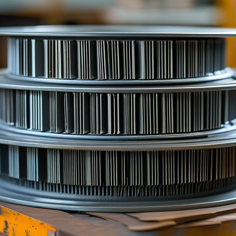
Laminated core transformers use stacked steel sheets to guide magnetic flux through a controlled path. A core is not one solid block. Each lamination usually measures about 0.23 to 0.30 millimeters and carries an insulating coating. This construction interrupts circulating eddy currents, reducing heat and wasted energy. The magnetic path runs through the center limb, upper yoke, outer limbs, and lower yoke. Small details matter. Poorly fitted joints can increase reluctance and create local hot spots.

Grain-oriented electrical steel improves flux movement along the rolling direction. Engineers therefore align laminations carefully, especially around mitered corners. A practical inspection checks burrs, clamping pressure, coating damage, and air gaps. Even a narrow gap can raise magnetizing current and audible hum.

The U.S. Department of Energy’s 2016 technical support document estimated 3.63 quadrillion Btu of energy savings over 30 years from improved distribution-transformer efficiency. That figure covers complete transformers, not laminated cores alone, but it shows why core losses deserve attention.

Magnetic flux should follow the shortest practical route. Shell-type cores surround more of the winding, while core-type designs place windings around the limbs. Both use laminations, yet their cooling and mechanical behavior differ. IEC 60076-1 provides the wider framework for transformer testing and performance. In real workshops, perfect joints are difficult. A small manufacturing compromise may look harmless, then become measurable during no-load testing.

Toroidal Cores: Compact Design and Operating Features

What Are the Main Transformer Core Types?

Toroidal Cores: Compact Design and Operating Features

Toroidal cores use a continuous ring of magnetic material. This geometry gives the winding a short magnetic path and reduces air gaps. In practical assemblies, copper wire wraps evenly around the ring, resembling a tightly wound spool. That structure can lower leakage flux and audible vibration. It also supports compact equipment designs where height and surface area matter.

The U.S. Department of Energy’s 2016 transformer technical support document evaluates efficiency through no-load and load losses over a 30-year analysis period. Toroidal construction can help reduce no-load loss, especially when the core uses suitable grain-oriented electrical steel. However, core material, flux density, winding tension, and insulation quality still control the result. The shape alone is not a guarantee.

Quiet operation matters.

IEC 60076-1 provides the general framework for transformer ratings, testing, and operating conditions. Engineers should verify temperature rise, inrush current, regulation, and mechanical clearance under the intended load. A toroidal transformer may deliver strong efficiency in a compact enclosure, but its winding process can be slower and more difficult to inspect. I have seen designs that looked excellent on paper yet needed better clamping to control startup noise. That limitation deserves attention. Reliable selection requires measured loss data, thermal tests, and documentation traceable to the applicable standard.

Ferrite Cores for High-Frequency Transformer Applications

Transformer cores guide magnetic flux through the windings. Common shapes include EI, EE, toroidal, and pot cores. For high-frequency work, ferrite is often the practical choice because its high electrical resistance limits eddy-current losses.

Ferrite cores are made from ceramic magnetic materials, commonly based on manganese-zinc or nickel-zinc compositions. MnZn ferrites suit many power converters, while NiZn materials can support higher-frequency signal applications. Core shape also matters. EE and EI cores provide accessible winding windows and simple assembly. Toroidal cores reduce leakage but can be harder to wind. Pot cores offer shielding and compact construction.

In bench testing, I check core temperature, switching frequency, and waveform distortion together. A core that appears efficient at room temperature may overheat inside a sealed enclosure. The selected material must handle the expected flux density without entering saturation. An air gap can store energy, but it may increase fringing losses. Keep it intentional.

Winding layout deserves equal attention. Shorter turns reduce leakage and unwanted capacitance. Insulation spacing must match the working voltage and applicable safety requirements. I have seen designs fail because engineers focused only on the core’s power rating. That rating is not universal. The first selection is rarely perfect. Rechecking losses under real load often reveals a better ferrite geometry or gap.

Air-Core Transformers and Their Specialized Uses

What Are the Main Transformer Core Types? Air-Core Transformers and Their Specialized Uses

Air-core transformers use coils without iron or ferrite inside the magnetic path. This design prevents core saturation and reduces hysteresis loss at high frequencies. It suits radio-frequency circuits, wireless power links, impedance matching, and laboratory pulse equipment. A visible coil may sit on a small plastic former, with a few millimeters between windings. That gap affects coupling, leakage, and tuning.

MarketsandMarkets estimated the overall transformer market at $58.7 billion in 2024. Its forecast reaches $82.9 billion by 2029, showing stronger demand for specialized designs. Air-core units remain a niche within that market. Their value comes from frequency performance, not bulk power handling. In RF equipment, engineers can tune inductance by changing coil spacing or winding geometry. This flexibility is useful during prototyping.

The trade-off is important. Air cores usually need more turns or higher current for the same energy transfer. Magnetic coupling is weaker, and nearby metal can distort the field. Electromagnetic interference may also become troublesome. IEEE transformer guidance supports careful insulation, thermal, and creepage evaluation, even when no magnetic core exists. A recurring design mistake is treating air-core efficiency as automatic. It is not. In practice, measurement often reveals unexpected losses from copper resistance, skin effect, and poor alignment. Grand View Research’s recent industry analyses also point to expanding high-frequency and wireless-power applications, but market forecasts cannot replace bench testing. A small thermal camera and an impedance analyzer may expose more truth than a promising simulation.

What Are the Main Transformer Core Types? - Air-Core Transformers and Their Specialized Uses
Transformer Core Type Core Material or Structure Magnetic Behavior Typical Frequency Suitability Main Advantages Key Limitations Specialized Uses
Air-Core Transformer Winding geometry with air or another nonmagnetic medium forming the magnetic path No magnetic-core saturation; coupling depends strongly on coil spacing, alignment, and geometry High-frequency and radio-frequency applications; the practical range depends on winding design and parasitic effects Very low core loss, no hysteresis loss, no core saturation, and good performance at high frequency Low inductance and lower magnetic coupling than many closed-core designs; magnetic fields can spread into surrounding space RF coupling, antenna and impedance-matching networks, resonant circuits, wireless power links, Tesla-coil systems, and wideband pulse or signal transformers
Laminated Silicon-Steel Core Thin insulated electrical-steel laminations assembled into a magnetic circuit High permeability at power frequency with reduced eddy-current loss compared with a solid steel core Primarily utility and low-frequency power applications, commonly around 50–60 Hz High magnetic flux capability, robust construction, and efficient low-frequency power transfer Core loss and heating increase as frequency rises; laminations add weight and manufacturing complexity Power-frequency isolation transformers, distribution transformers, control transformers, and low-frequency audio transformers
Ferrite Core Soft magnetic ceramic, usually based on iron oxides combined with other metal oxides High electrical resistivity greatly limits eddy currents at elevated frequency Switching-power and radio-frequency designs, commonly from tens of kilohertz into the megahertz region depending on ferrite formulation Low high-frequency core loss, compact size, and good electromagnetic performance Lower saturation flux density than many metal cores; performance changes with temperature, frequency, and operating flux Switch-mode power supplies, high-frequency isolation transformers, flyback transformers, RF transformers, and common-mode chokes
Powdered-Iron Core Finely divided magnetic particles insulated from one another and pressed into a distributed-gap core Distributed air gap provides useful energy storage and gradual inductance reduction under increasing current Low- to medium-frequency power conversion and RF applications, depending on powder composition Good energy-storage capability, controlled permeability, and useful resistance to sudden saturation Higher core loss than some ferrites at high frequency; material properties vary significantly by formulation Output inductors, energy-storage chokes, resonant converters, RF tuning circuits, and impedance-matching networks
Amorphous-Metal Core Very thin ribbons of non-crystalline magnetic alloy, commonly used in wound-core forms Low hysteresis loss and favorable magnetic properties at power frequency Power-frequency and selected medium-frequency applications Lower no-load core loss than many conventional electrical-steel designs and good magnetic efficiency Material and processing costs can be higher; the ribbon is thin and may require careful mechanical handling Energy-efficient distribution transformers, high-efficiency power transformers, and selected power-electronic magnetic components
Nanocrystalline Core Very fine-grained magnetic alloy produced through rapid solidification and controlled heat treatment High permeability with low loss over a broad frequency range when operated within design limits Medium-frequency power electronics, high-frequency filtering, and precision magnetic applications High permeability, compact magnetic components, and strong common-mode attenuation performance Higher material cost and sensitivity to mechanical stress, temperature, and operating conditions Common-mode noise filters, current transformers, high-frequency transformers, and power-quality equipment
Gapped Ferrite Core Ferrite core containing a deliberate air gap in the magnetic path Air gap lowers effective permeability and increases energy-storage capacity while reducing abrupt saturation High-frequency power conversion, commonly from tens of kilohertz upward depending on material and design Suitable for storing magnetic energy and handling direct-current bias in inductive components The gap increases magnetizing current and fringing fields; incorrect gap design can increase losses Flyback transformers, energy-storage inductors, boost converters, and forward-converter output magnetics
Actual operating frequency, power level, insulation rating, and efficiency depend on core material, geometry, winding construction, cooling, and the specific circuit design.
Need Help?
X

Ready to Talk?

Our team is ready to connect.