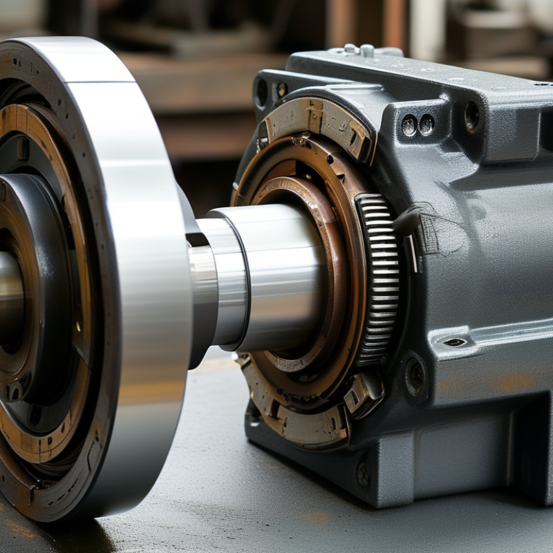
What Is a Motor Rotor Shaft and How Does It Work?

A Motor Rotor Shaft is the rotating backbone of an electric motor. It transfers mechanical power from the rotor to a fan, pump, gearbox, or other driven equipment. Although the shaft may look like a simple metal cylinder, its design affects efficiency, vibration, noise, and service life.

Inside the motor, electromagnetic forces make the rotor turn around the stationary stator. The rotor shaft supports this rotating assembly and carries torque through a keyway, spline, threaded end, or direct coupling. Bearings hold the shaft in position while allowing smooth rotation. Small alignment errors can create noticeable vibration. Heat, load changes, and poor lubrication can also affect performance.

Material selection matters. Engineers often use alloy steel because it combines strength, toughness, and fatigue resistance. The shaft diameter, surface finish, balance, and tolerance must match the motor’s operating conditions. During maintenance, technicians may inspect journal surfaces, measure runout with a dial indicator, and check for scoring or unusual wear. These practical checks often reveal problems before a failure occurs.

The working principle is clear.

The details are not always simple.

A damaged rotor shaft can reduce output, increase bearing stress, or cause sudden shutdowns. However, shaft failures do not always come from the shaft itself. Coupling misalignment, excessive loads, or installation mistakes may be responsible. This article explains how a Motor Rotor Shaft works, how engineers design it, and how reliable inspection supports safer, longer-lasting motor operation. Exact service requirements still depend on the manufacturer’s specifications and the motor’s application.

What Is a Motor Rotor Shaft and How Does It Work?

Motor Rotor Shaft: Definition and Core Components

A motor rotor shaft is the central mechanical member that carries the rotating assembly. It transfers torque from the rotor to a coupling, gear, fan, or driven load. Inside the motor, it supports the rotor core and maintains a controlled air gap around the stator. The shaft commonly includes bearing seats, shoulders, threads, keyways, and a machined coupling end. These are core components, not decorative details. A slight dimensional error can create vibration, noise, or uneven bearing wear.

During operation, electromagnetic force turns the rotor, and the shaft delivers that rotation outward. Bearings hold the shaft in position while allowing smooth movement. The rotor core is usually fixed near the shaft center, often through a press fit, key, or other engineered connection. A keyway helps prevent slipping between the shaft and a mounted component. In high-speed motors, dynamic balancing becomes especially important. That sounds simple. Yet heat, load changes, and misalignment can gradually affect shaft performance.

Reliable shaft design depends on material strength, surface hardness, runout control, and accurate machining. In practical maintenance work, inspectors check scoring, cracks, corrosion, and damaged threads. They also measure runout with suitable precision equipment. Surface damage may look minor, but it can concentrate stress during rotation. Engineers must also consider thermal expansion and the shaft’s critical speed. No design is perfect. A stronger shaft may add weight, while a lighter shaft may respond poorly to shock loads. Actual operating conditions should guide the final design and inspection method.

How the Rotor Shaft Transfers Mechanical Power

A motor rotor shaft is the rotating member that carries mechanical power from the rotor to a connected machine. Inside the motor, electrical energy creates a magnetic field around the rotor. This field produces torque, causing the rotor and shaft to spin together. The shaft then delivers that rotation through its end, often to a pulley, fan, pump, gearbox, or coupling.

Torque is the shaft’s turning force. Speed describes how quickly it rotates. Their relationship determines the useful mechanical output. A shaft spinning at 1,800 revolutions per minute can drive equipment directly, or it can pass through gears to increase torque and reduce speed. Keyways, splines, or threaded ends help transfer force without unwanted slipping. A coupling also helps align the motor with the driven load.

Bearings support the shaft while allowing smooth rotation. Lubrication, alignment, and balanced rotor construction reduce friction and vibration. During inspection, technicians often check for scoring, bending, unusual noise, and excessive heat near the bearing seats. A shaft may look straight but still produce harmful vibration. That detail is easy to miss. Real installations are less tidy than diagrams, especially when flexible couplings, heavy loads, or frequent starts are involved. Small alignment errors can gradually damage seals, bearings, and the connected equipment.

How a Motor Rotor Shaft Transfers Mechanical Power

The rotor shaft transfers torque from the rotating rotor to the driven machine. Mechanical power is calculated as P = 2πnT / 60, where P is power in watts, n is rotational speed in revolutions per minute, and T is torque in newton-metres.

At a constant speed of 1,500 rpm, increasing shaft torque produces a proportional increase in transmitted mechanical power. The values shown are calculated from the standard rotational-power equation.

Key Forces and Loads Acting on a Rotor Shaft

What Is a Motor Rotor Shaft and How Does It Work?

Key Forces and Loads Acting on a Rotor Shaft

A rotor shaft transfers motor torque from the electromagnetic assembly to the driven equipment. Torque is not harmless. It creates torsional stress, especially during starting, sudden loading, or repeated speed changes. In practice, I check the shaft diameter, material strength, and keyway area because small geometric changes can raise stress sharply.

Radial loads come from rotor weight, magnetic imbalance, belt tension, and imperfect alignment. Bearings support these forces, but they do not remove them. A shaft may appear straight while producing noticeable vibration at operating speed. During inspection, technicians often examine bearing journals for scoring, discoloration, or uneven contact marks. These details can reveal overload before a serious failure occurs.

Axial loads act along the shaft length. They may result from helical gears, thrust-producing couplings, or thermal expansion. Heat changes the fit. If the shaft expands against a fixed bearing, internal forces can increase unexpectedly. Torsional vibration also deserves attention because fluctuating torque may cause fatigue cracks near shoulders, keyways, and threads. A simple stress calculation is useful, but it is not enough. Real systems include misalignment, assembly errors, and changing loads. That assumption is imperfect. Engineers should compare calculations with vibration data, temperature readings, and inspection results before selecting shaft dimensions or maintenance intervals.

What Is a Motor Rotor Shaft and How Does It Work? - Key Forces and Loads Acting on a Rotor Shaft

Illustrative Rotor-Shaft Load Assessment for a 15 kW, 3,000 rpm Motor
Load or Force Primary Cause Typical Relationship Illustrative Value Effect on the Shaft Key Design Check
Transmitted torque Electromagnetic torque transferred from the rotor to the driven machine T = P / ω 47.7 N·m at 15 kW and 3,000 rpm Produces torsional shear stress and angular twist Check torsional strength, fatigue life, keyways, splines, and couplings
Starting or transient torque Motor acceleration, sudden load changes, or fault events Tpeak = K × Trated 95.4 N·m when K = 2.0 Raises torsional stress and may excite torsional vibration Verify transient strength and separation from torsional natural frequencies
Centrifugal force from unbalance Residual mass eccentricity in the rotor assembly Fu = Uω² 197 N for U = 0.002 kg·m at 3,000 rpm Creates rotating radial force, vibration, and bearing loading Control balance quality, runout, vibration velocity, and bearing loads
Radial bending load Rotor weight, belt pull, gear forces, coupling offset, and magnetic pull M = F × L 25 N·m for a 500 N radial load at a 50 mm overhang Produces bending stress and shaft deflection Check combined bending and torsion, deflection, and fatigue at shoulders
Bearing reaction force Support reactions caused by rotor weight, unbalance, and external loads ΣF = 0; ΣM = 0 Approximately 250 N per bearing in a symmetric static case Transfers radial and sometimes axial loads into the bearings Check bearing rating, lubrication, alignment, and housing stiffness
Axial thrust Helical gears, fan pressure, hydraulic forces, or magnetic asymmetry Fa = Δp × A or manufacturer load data 120 N for a 20 kPa pressure difference over 0.006 m² Loads the locating bearing and can shift the rotor axially Check thrust capacity, axial clearance, thermal growth, and end-float control
Thermal load Temperature gradients, friction, rotor losses, and restricted heat dissipation ΔL = αLΔT 0.036 mm growth for a 300 mm steel shaft and a 30°C rise Changes clearances, preload, alignment, and bearing loads Allow for thermal expansion and maintain suitable fits and clearances
Torsional vibration Cyclic electromagnetic torque, variable-speed operation, or drivetrain resonance fn = (1/2π)√(kt/J) Must be evaluated against operating excitation orders Causes alternating shear stress and possible fatigue damage Perform modal analysis and avoid continuous operation near resonance
Critical-speed response Natural bending frequency aligning with rotational speed ncritical ≈ 60fn A 50 Hz bending mode corresponds to approximately 3,000 rpm Amplifies shaft deflection, vibration, and bearing forces Check rotor dynamics, damping, balance, and operating speed margins
Reference conditions: The numerical values are engineering examples calculated for a 15 kW motor operating at 3,000 rpm. Actual rotor-shaft loads depend on rotor mass, span, bearing arrangement, coupling type, driven equipment, balance condition, temperature, and operating transients.

Common Materials and Manufacturing Methods

What Is a Motor Rotor Shaft and How Does It Work?

Common Materials and Manufacturing Methods

A motor rotor shaft is the mechanical spine of a rotating assembly. It carries torque from the rotor to a gearbox, pump, fan, or driven machine. The shaft must resist bending, twisting, vibration, and repeated thermal cycles. The International Energy Agency has reported that electric motor systems consume nearly half of global electricity. Small efficiency losses can therefore create large operational costs.

Common shaft materials include medium-carbon steel, alloy steel, and stainless steel. Alloy steel is widely selected when higher fatigue strength and impact resistance are required. Stainless steel suits humid or corrosive environments, but it can cost more and require careful machining. Aluminum reduces weight, although its lower stiffness limits some high-speed designs. Material selection is never perfect.

Manufacturing usually begins with forged or rolled bar stock. Forging can improve grain flow around highly loaded sections. Turning creates the basic diameter and shoulders. Keyways, splines, and threaded ends are then machined. Heat treatment can increase hardness and fatigue resistance, followed by grinding for tight tolerances. The U.S. Department of Energy’s motor-system guidance emphasizes alignment, balancing, and efficient operation as major reliability factors. Runout matters. Even a small dimensional error can amplify vibration at high speed. ISO 21940 balancing practices are commonly applied before final assembly, although real operating conditions may expose weaknesses that factory testing misses.

Maintenance Issues and Performance Considerations

A motor rotor shaft is the rotating core that transfers electromagnetic torque to a machine’s load. It supports the rotor, aligns with the bearings, and carries the output through a coupling, fan, or gear. Its performance depends on accurate balance, suitable material strength, and stable bearing support. A small bend can create large vibration at operating speed.

Maintenance problems usually begin quietly. Inspectors should check bearing temperature, shaft runout, coupling alignment, and vibration trends. ISO 20816 guidance treats vibration as a key indicator of rotating-machine condition, but one reading is not enough. A clean reading can still be misleading. Trends reveal deterioration more reliably. Look for fretting marks, oil contamination, electrical pitting, and unusual rotor noise. These details often appear before a serious failure.

Efficiency also matters. The International Energy Agency has reported that electric motor systems use roughly 46% of global electricity. The U.S. Department of Energy states that motor-driven systems can consume more than half of industrial facility electricity. Poor alignment increases friction and current demand. Excessive shaft clearance can reduce torque transfer and damage bearings. Technicians should record load, speed, temperature, and vibration together. Replacing a shaft without correcting the root cause is an incomplete repair. Sometimes the maintenance plan is the real failure. Regular balancing and alignment checks remain practical, although they are often postponed during production pressure.

Need Help?
X

Ready to Talk?

Our team is ready to connect.