7 Tips to Read an LCD TV Circuit Diagram?

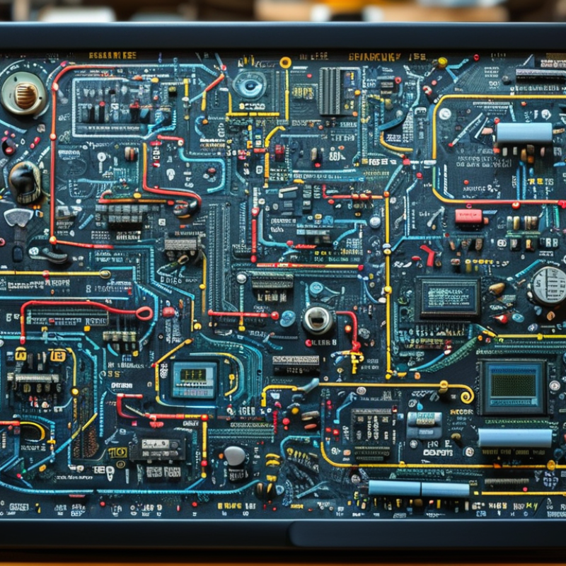
Reading an LCD television board can feel like tracing a city at night, with tiny roads, symbols, and power lines crossing the screen. A clear Lcd Tv Circuit Diagram turns that confusion into a practical map. It shows how the power supply, mainboard, timing controller, backlight, audio section, and panel communicate.

This guide presents seven useful tips for reading these diagrams with greater confidence. Each tip connects symbols to physical parts, such as a fuse near the AC input or a ribbon cable leading toward the display panel. Experienced technicians often compare the diagram with board markings, connector labels, and measured voltages. That simple habit prevents many incorrect assumptions.

Safety matters throughout the process. Television circuits may contain dangerous voltages, even after unplugging the set. A qualified technician should handle live testing and discharge procedures. The guide also encourages careful documentation, including clear photographs, connector notes, and resistance readings. Small details can reveal a failed regulator or a broken signal path.

Not every diagram is complete.

Manufacturers may use different symbols, abbreviations, or revision numbers. Some service documents contain unclear labels, and personal interpretation can introduce mistakes. Recognizing that limitation supports better troubleshooting. Rather than replacing parts randomly, readers can follow power flow, confirm reference points, and compare expected readings with actual results. This approach combines practical experience, technical knowledge, and reliable service documentation. It also helps beginners understand why a circuit behaves differently from its simplified drawing.

7 Tips to Read an LCD TV Circuit Diagram?

Identify the Main Sections and Symbols in an LCD TV Circuit Diagram

Reading an LCD TV circuit diagram becomes easier when you identify its main sections before tracing signals. The power supply section usually appears near the AC input and contains fuses, rectifiers, transformers, capacitors, and voltage regulators. The main board handles processing, audio, control signals, and communication. A timing-control section sends image data toward the panel, while the backlight circuit drives the LEDs behind the screen. Look for connector labels such as power, data, ground, and control.

Tip: Trace the circuit by function, not only by physical position. A symbol with three lines often represents ground. A triangle may indicate a diode, while a rectangular block can represent an integrated circuit. Resistors limit current, capacitors store charge, and coils filter or transfer energy. Symbols can vary slightly between diagrams, so check the legend carefully. Small labels matter.

When I first studied a diagram, I followed every line and quickly lost track. A better method is marking one signal path with a pencil, from input to output. Use different colors for power, video, and control lines. Pay attention to arrows, connector pin numbers, and test points. Never assume two similar connectors have identical functions. I once overlooked a ground symbol and misunderstood the entire section. That mistake was useful. Always compare the drawing with the board layout, and work only after the set is safely unplugged.

7 Tips to Read an LCD TV Circuit Diagram? - Identify the Main Sections and Symbols in an LCD TV Circuit Diagram

Tip Main Section Common Symbols How to Identify It Typical Circuit Function Reading Check
1. Trace the power path first AC input and primary power supply Fuse, switch, varistor, bridge rectifier, electrolytic capacitor, transformer Usually located near the AC input connector and separated from low-voltage circuitry by an isolation boundary. Converts incoming AC into regulated DC rails for the television circuits. Follow the path from AC Line and Neutral through protection, rectification, switching, and isolation.
2. Separate primary and secondary sides Isolated power-supply boundary Isolation transformer, optocoupler, chassis ground, secondary ground Look for a printed isolation line or clearance gap around the transformer and feedback components. Transfers energy while electrically isolating hazardous mains voltage from user-accessible circuits. Do not assume primary ground and secondary ground are electrically identical; verify the diagram markings.
3. Recognize the low-voltage rails Secondary power outputs Regulator IC, inductor, diode, filter capacitor, test point, connector Outputs are commonly labeled with rail names such as standby, main supply, logic supply, or panel supply. Provides stable DC voltages for the main board, timing controller, audio circuits, and display electronics. Check polarity, ground reference, enable signals, and the rated voltage printed beside each connector pin.
4. Follow signal flow through the main board Main processing and control board Processor IC, memory, crystal oscillator, HDMI or video connector, transistor, voltage regulator It connects external input ports to the display, audio, power, and user-control circuits. Processes video and audio, manages startup, and exchanges control data with other boards. Read arrows and connector labels from input source to processor, then toward the display and audio outputs.
5. Identify the display data path Timing controller and panel interface Flat-flex connector, differential data pairs, clock line, buffer IC, panel power filter The timing-controller section is positioned between the main board and the LCD panel, often using a wide ribbon cable. Converts processed video data into synchronized row and column information for the panel. Distinguish power pins from high-speed data pairs; the diagram may identify differential pairs by positive and negative labels.
6. Read the backlight driver separately LED backlight power and control LED symbol, boost inductor, switching MOSFET, rectifier diode, current-sense resistor, PWM input Located near a connector labeled for LED output, dimming, brightness control, or backlight enable. Raises and regulates voltage for LED strings while controlling brightness and protecting against overcurrent. Look for feedback from the LED string and a control line such as enable or pulse-width dimming.
7. Use reference designators and test points Component-level troubleshooting R = resistor, C = capacitor, D = diode, Q = transistor, L = inductor, F = fuse, TP = test point, CN = connector Each component has a unique reference number, while nets and connectors often carry functional labels. Links the schematic to the physical board and helps locate components, signal paths, and measurement points. Compare the component symbol, reference number, polarity marking, and expected measurement before replacing a part.
Safety note: The primary side of an LCD television power supply can contain hazardous mains voltage and charged capacitors even after disconnection. Use the circuit diagram, proper test equipment, and safe electrical procedures when taking measurements.

Trace Power Distribution from the Input Stage to Each Circuit Board

7 Tips to Read an LCD TV Circuit Diagram

Trace power from the input stage, not from the largest board. In my repair work, I follow the path from the AC connector through the fuse, filter, bridge rectifier, and bulk capacitor. The primary section usually feeds a switching transformer. Never assume a thick trace carries the main supply. Verify it against the schematic and board labels.

Tip 1 Mark each voltage rail with a pencil. A simple sketch prevents repeated mistakes.

After the transformer, identify the secondary ground and measure each output rail. Common rails include standby voltage, main logic power, audio power, and backlight supply. The standby rail often reaches the control board before the set turns fully on. A control signal then activates additional rails.

Tip 2 Separate standby paths from switched paths. They may share connectors but serve different purposes.

I once followed a return line incorrectly because the diagram placed it far from the related circuit. Diagrams can mislead.

Use connector pin numbers to trace power toward the main board, timing board, panel circuits, and LED driver. Check voltage names, polarity marks, and enable signals together.

Confirm the load before blaming the power board. A shorted downstream circuit can pull a healthy rail low. Disconnecting boards may help, but only with proper procedures and discharge precautions.

Tip 3 Confirm the load before blaming the power board.

Mains sections remain dangerous after unplugging. Use an isolated, correctly rated meter and follow an approved service manual. My notes are not flawless, so I recheck every measurement before replacing parts.

Follow Signal Paths Through the Video, Audio, and Control Circuits

7 Tips to Read an LCD TV Circuit Diagram?

Follow Signal Paths Through the Video, Audio, and Control Circuits

An LCD television diagram becomes clearer when you trace signals, not components. Start at the input connector. HDMI data usually moves into the main processor, where decoding, scaling, and timing occur. The video path then reaches the timing controller, source drivers, and finally the LCD panel. Mark each voltage rail with a pencil. A missing 12-volt line can explain a dark screen, but it does not prove the panel is defective.

Audio follows a different route. The processor extracts digital audio, then sends it to an amplifier or audio codec. Follow the lines toward the speakers. Look for mute, standby, and volume-control signals. A service report from the Consumer Technology Association found that televisions remain present in about nine out of ten U.S. households. That scale makes accurate board-level diagnosis valuable. Still, household ownership is not a repair statistic.

Control circuits are easier to miss. Trace the power-management IC, infrared receiver, keypad lines, and system-control bus. Watch for labels such as BL_ON, DIM, ENABLE, and STBY. Omdia’s 2024 display research estimated global television shipments near 208 million units, showing how widely these architectures are deployed. I sometimes mistake a control fault for a video failure. That mistake is useful. Recheck the signal direction, measure under load, and compare expected waveforms with actual readings. A diagram shows intent, not always reality.

Use Voltage Labels and Component Values to Check Circuit Operation

7 Tips to Read an LCD TV Circuit Diagram?

Voltage labels and component values turn a crowded LCD TV diagram into a practical test plan. I mark the power path first, from the AC input through rectification, switching, regulation, and panel supply. A labeled 12 V rail should measure close to 12 V under normal load, not merely show continuity. Always compare readings with the service specification and use an isolated, properly rated meter. IEC 62368-1 emphasizes energy hazards and protective barriers, so probe placement matters as much as the number.

Component values reveal whether a voltage makes sense. A 1 kΩ resistor carrying 12 V should draw about 12 mA, based on Ohm’s law. A shorted diode can collapse a rail, while a swollen capacitor may increase ripple without changing the average voltage. The U.S. Department of Energy’s television test procedures use defined operating conditions, reminding technicians that measurements need consistent brightness, input, and warm-up settings. Small changes matter.

I usually record the voltage before replacing parts. It prevents guesswork. Omdia’s 2024 TV market analysis reported millions of annual television shipments worldwide, which means repair decisions affect a large installed base. Still, diagrams are not perfect maps; revisions and board substitutions can create confusing labels. I once trusted a printed value too quickly. The connector pinout corrected me. Check ground references, polarity marks, and nearby test points before judging a circuit.

Apply Safety Procedures When Testing Live LCD TV Circuits

7 Tips to Read an LCD TV Circuit Diagram: Apply Safety Procedures When Testing Live LCD TV Circuits

Reading an LCD TV circuit diagram starts with identifying the mains input, rectifier, power supply, controller, and backlight sections. However, live testing requires more than diagram knowledge. A rectifier can produce about 325 volts DC from a 230-volt AC supply. The voltage may remain after unplugging. I always check the primary filter capacitor before touching the board.

Use an appropriately rated CAT III or CAT IV meter, insulated probes, and dry, nonconductive footwear. Keep one hand away from the chassis when practical. Never defeat protective earth or rely on an isolation transformer as complete protection. OSHA recommends de-energizing equipment whenever possible, while NFPA 70E emphasizes an electrically safe work condition. The U.S. Bureau of Labor Statistics reported 145 fatal occupational injuries involving electricity in 2022. That number makes rushed probing difficult to justify.

Mark test points directly on the diagram. Compare the measured voltage with the circuit’s expected value, not a guess. Backlight driver outputs can exceed the meter’s safe range. A probe slip can damage a controller or cause an arc. I still pause before every live measurement. That pause is useful. Diagrams can be incomplete, and my first interpretation can be wrong. When the circuit behaves unexpectedly, power down, discharge capacitors with approved equipment, and review the measurement path before trying again.

Need Help?
X

Ready to Talk?

Our team is ready to connect.